Pulse Delay Generator
For our experiment in double EIT, we needed to adjust the relative delay and duration of the two pulses which were sent to the atoms. The pulses were created by sending the beams through an AOM and switching the driving signal to the AOM on and off for a fixed period of time (typically a micro-second or so.) The AOM driver is switched with a TTL signal.
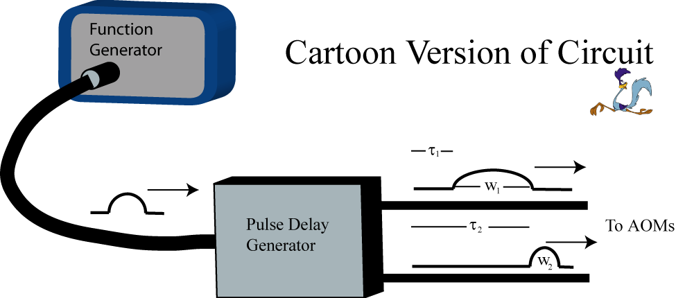
The design requirements were then the following: upon receiving a trigger signal, output a pulse into two separate channels. The delay and duration of the pulses should be independently programmable (fig 1.)
The heart of the circuit is the monostable multivibrator (MSMV). What a name. Monostable means that the device is in a stable state (low) when left on its own. If it gets trigger signal, it is put in the other state (high) for a fixed duration set by external capacitors and resistors, after which it returns to its stable state, awaiting the next trigger. Trigger can be a rising or falling edge. By using two multivibrators in series, we can create a pulse of a given duration as shown in figure 2.
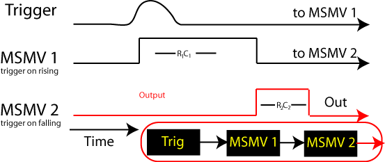
The output of MSMV 1 is fed directly to the input of MSMV 2. The first MSMV is set to trigger on the rising edge, while the second triggers on falling edge. Upon arrival of the trigger signal, the output of MSMV1 goes high for a peried determined by it's external resistors R1 and C1 (actually, in general it is some constant k times R1C1, but you get the idea.) As MSMV1 returns to low, the falling edge triggers an output pulse from MSMV2 of duration R2C2. This way we have a pulse of a prorammable duration emmited after a programmable delay from the trigger input.
For controlling the relative delay of two pulses, we just send the trigger to two separate MSMV pairs. The schematic is shown in figure 3.
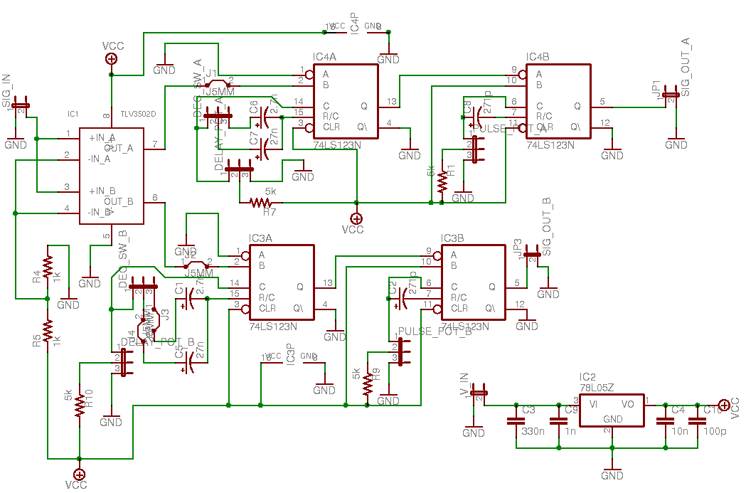
The trigger signal is passed through a fast dual comparator (TLV3502 from Texas instruments) which converts the pulse into two TTL pulses and decouples the circuit from the trigger device. For our monostable multivibrators, we used 74LS123N from Fairchild semiconductors, which conveniently comes in a package of two. According to the data-sheet the duration in the unstable high state is given by t[ns] = 0.36R[kOhm]C[pF]. We wanted pulses which had duration ranging from 500ns to 5000ns, delayed from anywhere between 1us to 100us. Since the delay spans two decades a x10 select switched between a 2.7nF and a 27nF capacitor. The delay is then adjusted by a resistor and potentimeter going from 1k to 5k yeilding a delay of 1 to 10 us as desired. Toggling the decad switch gives 10 to 100us. The second MSMV has C = 2.7nF and R from 500 to 5k, yeilding a pulse width from 500ns to 5us as desired. Each 74LS123 is outcoupled via a BNC jack and sent to the experiment.
The schematic and PCB trace was designed using cadsoft EAGLE software, and etched in our workshop. Below is a photo of the finished project.
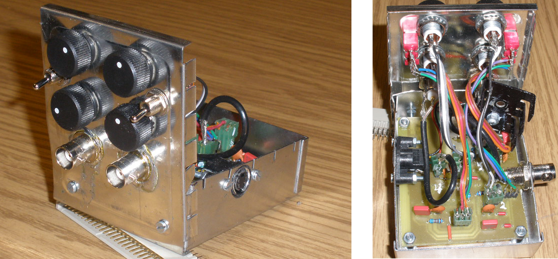
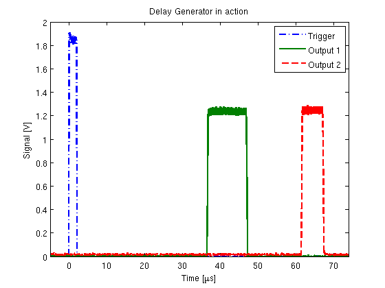
A sample oscilloscope trace of the pulse delay generator in action is shown below. The zipped EAGLE project eagle files may be found here